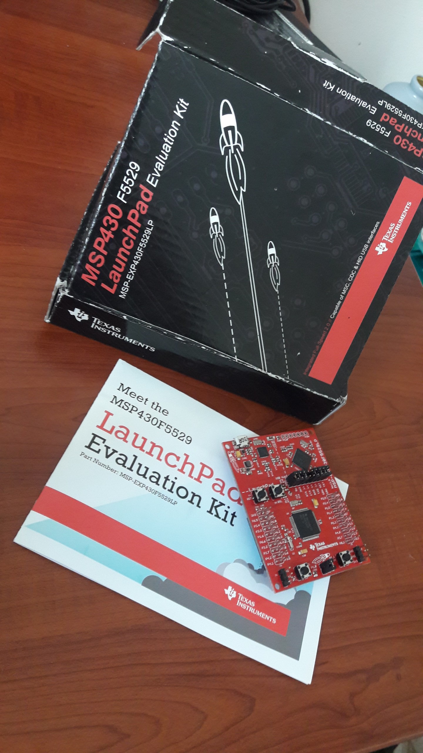
Hello everyone! I found a MSP board to discover 🙂 So that, I used an IDE/compiler different from Arduino IDE(or based) for the first time. I think it’s so important to use different IDEs, especially in low-level language. Using Arduino IDE isn’t like producing or creating, everything was simplified by others, we just download libraries and use them.

For example, I learned how pins work although it was my first application. I always wondered its principle, and now I know 🙂 of course without details. Let’s talk about pins…
I assume that you know what registers are. Actually, pins are related to registers; when we want to manage pins, we use registers to set them. And we’ll see this principle obviously in MSP programming. I’ll just write basics, if you want to read more detail, you can follow this link: Beginning with MSP430
Here is port2 register;
| PORT2 | Pin 5 | Pin 4 | Pin 3 | Pin 2 | Pin 1 | Pin 0 |
| 0 | 0 | 0 | 0 | 0 | 0 |
if we want to set pin2.0 to 1, we have to set Pin0 in Port2 to 1, so we use C operators like below:
[code]
P2DIR |= 0x01; //000001
[/code]
After this code line, our port2 values will be like below:
| PORT2 | Pin 5 | Pin 4 | Pin 3 | Pin 2 | Pin 1 | Pin 0 |
| 0 | 0 | 0 | 0 | 0 | 1 |
P2DIR: I’ve not been sure that yet, but I guess this variable was set as a default to reference port2 registers to set output/input state.
So now, let me show you an example for led blinking:
[code]
#include "io430.h"
volatile unsigned int i;
void main( void )
{
// Stop watchdog timer to prevent time out reset
WDTCTL = WDTPW + WDTHOLD;
P1DIR |= 0x01;
for(;;){
P1OUT^=0x01;
i=50000;
do(i–);
while(i!=0);
}
}
[/code]
So we came to the end of the post, so you can try to manage the other pins.


Leave a Reply