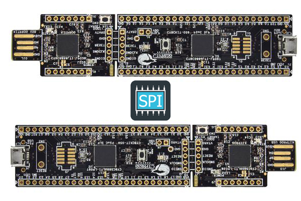
Hello again! In this post, we’ll observe SPI interface between PSoC 5LP devices, as you know before, there are some kind of communication methods like i2c, uart and SPI to provide exchanging information between modules or MCUs. Before we observe, I strongly recommend you should read the details about SPI from SparkFun or Wiki etc.
After you look at the details, we know that “implementation of SPI is different for different devices” so we have to observe behaviour of data/clock bus or we can look at the examples. They can help us to create our algorithm. Ok, we can start after look at some general informations.
In general, SPI works when SS bus is at LOW and CLK works. These two conditions are enough to exhange data which are on MISO or MOSI simultanously; also you can use this method as a request-response method without simultanously. You can verify this information on SparkFun article. But, as we mentioned before, implementation is different for different devices and these two conditions are not enough for PSoC devices. You have to send data to MOSI bus to start exchange/clock because you can’t control CLK, CLK is worked automatically by MCU when MOSI is filled (when WriteTxData() is called). In this post, we’ll design, code and analyze SPI between two PSoC devices 🙂
Master Side (Design, Code)
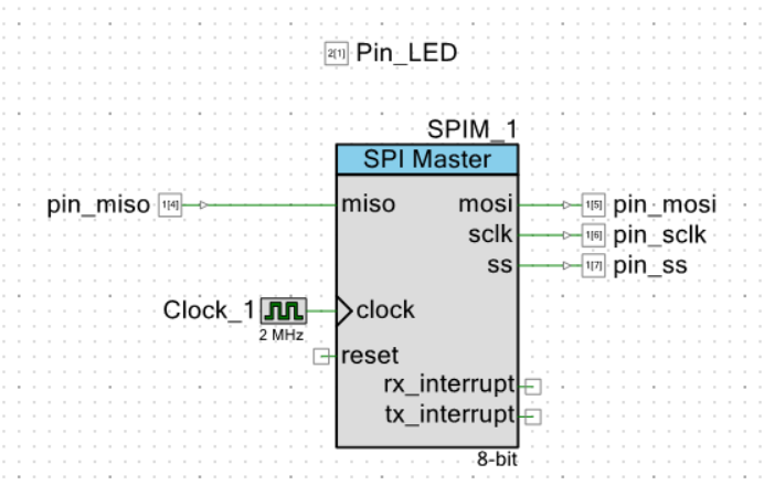
RX, TX buffer size are 4 byte for SPI Master. We’ll send and receive 4 byte data.
#include "project.h"

void sendDataToSlaveForRequest(){
    SPIM_1_WriteTxData(0x51);
    SPIM_1_WriteTxData(0x52);
    SPIM_1_WriteTxData(0x53);
    SPIM_1_WriteTxData(0x54);
}

int main(void)
{
    CyGlobalIntEnable; /* Enable global interrupts. */

    SPIM_1_Start();
    SPIM_1_ClearRxBuffer();
    SPIM_1_ClearTxBuffer();
    SPIM_1_ClearFIFO();

    Pin_LED_Write(0);

    CyDelay(50u);

    Clock_1_Start();

    sendDataToSlaverForRequest();

    //Wait until RX buffer gets full
    //*
    //I'll write something about this control at the end of the post
    while(!(SPIM_1_ReadRxStatus() & SPIM_1_STS_RX_FIFO_FULL));

    uint8 receivedDataBuffer[4];

    for(uint8 i=0;i<=3u;i++){
        uint8 data=SPIM_1_ReadRxData();
        receivedDataBuffer[i]=data;
    }

    Pin_LED_Write(1);

    for(;;)
    {
        /* Place your application code here. */
    }
}
Slave Side (Design, Code)
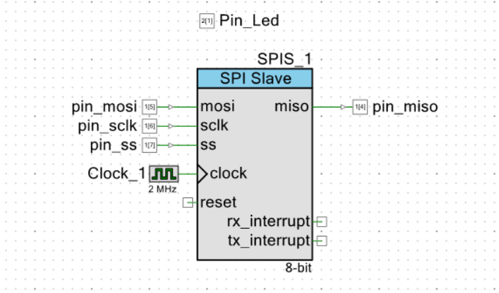
RX, TX buffer size are 4 byte.
#include "project.h"

void sendDataToMaster(){
    SPIS_1_WriteTxDataZero(0x35);
    SPIS_1_WriteTxData(0x36);
    SPIS_1_WriteTxData(0x37);
    SPIS_1_WriteTxData(0x38);
}

int main(void)

{
    CyGlobalIntEnable; /* Enable global interrupts. */

    SPIS_1_Start();
    SPIS_1_ClearRxBuffer();
    SPIS_1_ClearTxBuffer();
    SPIS_1_ClearFIFO();

    Pin_Led_Write(0);

    CyDelay(10u);

    while(!(SPIS_1_ReadRxStatus() & SPIS_1_STS_RX_FIFO_FULL));

    sendDataToMaster();

    Pin_Led_Write(1);

    for(;;)
    {
        //Place your application code here.
    }
}
RESULT
While devices working, we use a logic analyser to observe the exhanging.
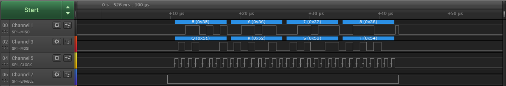
As you see the result, communication works correctly.
Now, there was a warn message at master main.c code on while() control. This control may have wrong value because I had this problem 🙂 when I run the master code without any slave device, this code block assumes that RX is full. After this result, when I analyze using logic analyser I saw that: When we send data on MOSI, if there is no data on MISO, random data are assigned on MISO bus. So be carefull and always analyse your communication using logic analyser.
Irshad Khan
Aslms Brother
Thank you for sharing your knowledge with us.
There is an error in your code:
sendDataToSlaverForRequest();
The r must come out, it is Slave not Slaver
Thanks Irshad Khan, Cape Town, ZA
funal
Thanks for the correction 🙂