
A long time since I posted the last time… I have been studying new topics. Today, I’d like to share a post about a DSP function on ARM processors. It is “convolution.”
Let’s begin with the definition. I can say that the magic keyword behind the convolution is “signal decomposition”. You should investigate their relationship. Also, you can also check out this chapter or this series. They describe the connection between impulse response and convolution function in a nutshell. I merely provide you with the source because I don’t have enough time to explain them from scratch or to make them animated.
Here is the discrete equation of the convolution:
![\[y[n]=h[n]{ }^{*} x[n]\]](https://unalfaruk.com/wp-content/ql-cache/quicklatex.com-86eae0519e0ab3a9027b9fef42fc4da9_l3.png "Rendered by QuickLaTeX.com")
![\mathrm{x}[\mathrm{n}]: N](https://unalfaruk.com/wp-content/ql-cache/quicklatex.com-eeecd430fb9471ff7581fd030676f301_l3.png "Rendered by QuickLaTeX.com") -point signal from 0 to
-point signal from 0 to 
![\mathrm{h}[\mathrm{n}]](https://unalfaruk.com/wp-content/ql-cache/quicklatex.com-3ba00cda96799decaf71cbb152e0d0ba_l3.png "Rendered by QuickLaTeX.com") :
:  -point signal from 0 to -1
![\mathrm{h}[\mathrm{n}]{*}\mathrm{x}[\mathrm{n}]: N+M-2](https://unalfaruk.com/wp-content/ql-cache/quicklatex.com-760014df9e844c97664766ca3a3f5c3d_l3.png "Rendered by QuickLaTeX.com") point signal from 0 to
point signal from 0 to 
![\[y[i]=\sum_{j=0}^{M-1} h[j] x[\mathrm{i-j}]\]](https://unalfaruk.com/wp-content/ql-cache/quicklatex.com-d7f65c6f9dbfa997d0360aed27468189_l3.png "Rendered by QuickLaTeX.com")
Let’s analyze a specific output point, how does it calculated…
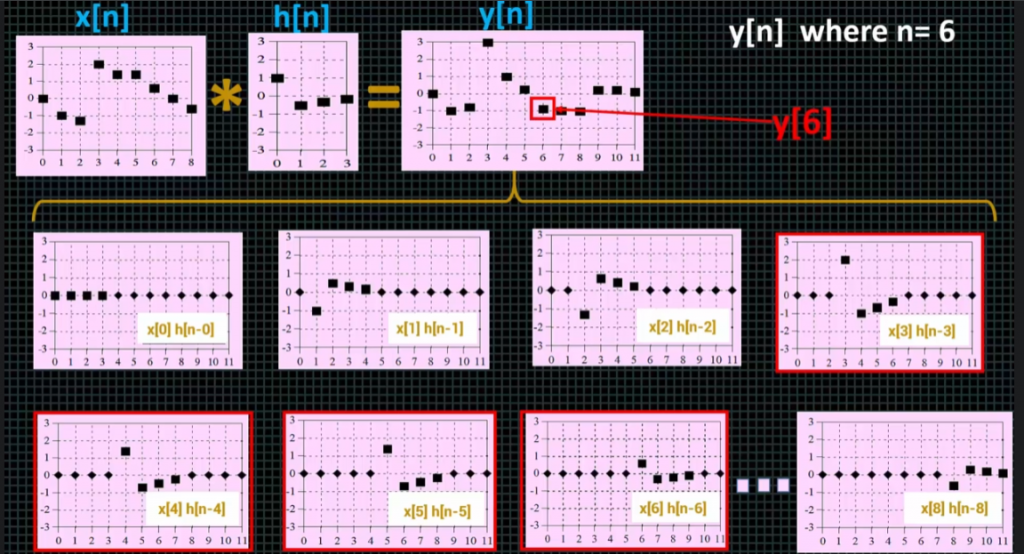
As can be seen from the explanation above, we can decompose the output signal to decide which scale/shift step of impulse response affects the 6th element at the output. The pattern can be seen clearly!
![y[n]= x[3]h[n-3] + x[4]h[n-4] + x[5]h[n-5] + x[6]h[n-6]](https://unalfaruk.com/wp-content/ql-cache/quicklatex.com-58b326765b12678caf2b891699030888_l3.png "Rendered by QuickLaTeX.com")
![y[6]= x[3]h[6-3] + x[4]h[6-4] + x[5]h[6-5] + x[6]h[6-6]](https://unalfaruk.com/wp-content/ql-cache/quicklatex.com-7bf78311f1da18115505e23d731130db_l3.png "Rendered by QuickLaTeX.com")
![y[6]= x[3]h[3] + x[4]h[2] + x[5]h[1] + x[6]h[0]](https://unalfaruk.com/wp-content/ql-cache/quicklatex.com-67ba9f411f70cf81e74a1368754570ef_l3.png "Rendered by QuickLaTeX.com")
So, the sum of i and j values which are index values of the input signal and the impulse response must be the same as the index value of the output signal which we’re analyzing. It is our algorithm…
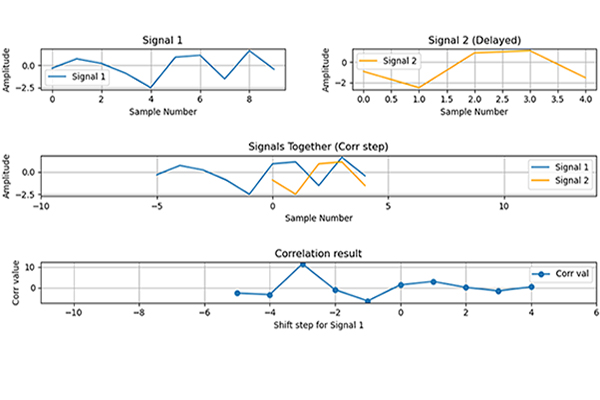
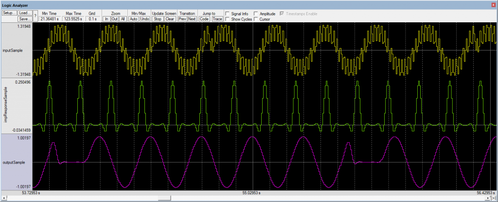
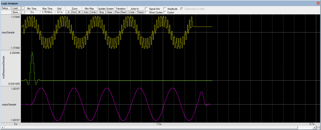
The signals on the logic analyzer:
It’s the first part of the post… CMSIS Convolution will be described and implemented in the next post…
I am waiting for your feedback… tips and tricks, or my faults, etc.
Leave a Reply